Panacea-BOCAF On-Line University
The educational series
covering
clean energy technology towards building our children a future. Panacea-BOCAF is a registered non-profit organization, dedicated
to educational study and research. All
copyrights
belong to their owners
and are acknowledged.
All material presented
on this web site is
either news reporting
or information presented for non-profit study and research, or has previously been publicly disclosed or has implicitly or explicitly been put into the public domain.
Fair Use applies. Contact us.
Overview�������������������������������������... Description������������������������������������� Replication�������������������������������������
Faculty information��������������������������������� Patents��������������������������������������... Technical
support forum������������������������������... Videos���������������������������������������
Resources�������������������������������������.. Credits���������������������������������������
Overview
The following overview
has been provided by Peter Lindermann.
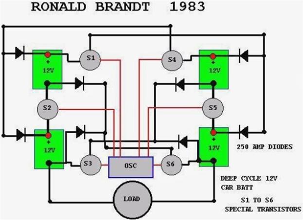
The original circuit was developed by Ronald Brandt.
The 1983 date of the Brandt
circuit
pre-dates John Bedini�s work on this system.
Ron's circuits used mechanical (as
opposed to solid state)
contractors as switches, but
apparently worked quite
well, as long as the contactors lasted.
John was the first to adapt this circuit to solid-state switching, using the SG 1524 dual flip-flop functions
and bipolar transistors as the switches.
John has told me that his "cigar box" unit ran
a small electric
motor for more
than
6 months without
discharging the batteries
AT ALL. He also told me that the original working model was smashed
by a "guest" in his shop
who was infuriated by its operation,
while John was out of the room. At this point, he decided not to rebuild it.
I know John personally, and have no reason to doubt this report. Obviously, the voltage
drops in the transistors and diodes present a CONSTANT loss
during operation, not
to mention the energy dissipated at
the load. Therefore, the system
defies all standard
explanations and energy use equations. The batteries apparently stay charged and run loads simultaneously for a reason that is not conventional. Since Ronald Brandt has run a car on this system, and John Bedini has run small motors
on miniaturized version, it seems reasonable to assume it is worthy
of more study by experimenters. It
is recommended that you
read a lengthy report; written by Eike
Mueller, dated September 3,
1984
entitled �EXPERIMENTS WITH
A KROMREY AND
A BRANDT-TESLA CONVERTER BUILT BY JOHN
BEDINI With Comments by Tom Bearden 1984 33 pages. Open source
Rick Fredrick has this booklet available for sale on his web site. Or you can down load this from the energetic
forum. Technical discussion links and related
links will be listed at the end of this
course.
Ed-Note
some engineers have experienced
failures from the circuits listed in this report.
These will be covered in the faculty
section; this is for a point of study in order to evaluate the process further.
This
paper discusses tests of this system.
Perhaps John would be willing to comment further on this at some point. But maybe he won't. After all, it
was John's demonstration of this system at the
Tesla Conference in 1984 that precipitated the events that culminated in having his life threatened if he continued his work on it. I know of
no one who has had their life threatened for working on a technology that didn't work! �End
The concept of this device is simply to allow the batteries
to self charge and run a load. Reports by
experimenters have stated
that even if the circuit is not
performing this self running
function, it still allows a better than normal
efficiency from the battery
arrangement. This so far has been shown in the mechanical or rotary switched version as opposed to solid state version.
Given the efficiency
reports by John Bedini
and these results, this is an invaluable power management process which the mainstream faculties must benefit from and must investigate further.
As a potential emission
cutting device and power savings
device alone, this technology justifies (and needs) law for its mandatory
implementation. Faculties
must endorse open source engineers and investigate or this
technology will continue to be held
back from the public.
The Nonprofit organization Panacea-BOCAF intends to
support open source engineers working
with the Tesla switch and other suppressed
clean energy technologies. These engineers require grants, resources, faculty recognition
and security. All this can be created in Panacea�s proposed granted research and development center. For those able to help
this
effort,
please Contact us.
Description
The name for this device comes from the original Eike
Mueller Kromrey
and Brandt
�Tesla converter� report which was built by
John Bedini. This
device has been coined as the �Tesla
Switch� or �Brandt switch�. The concept, which had originated
by Nikola
Tesla, was
given to John Bedini by Ronald Brandt, who
was a personal friend of Nikola
Tesla.
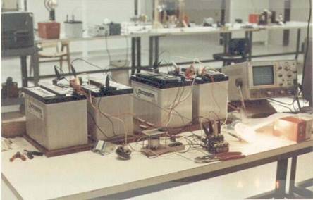
This is a
picture of
the
Tesla
Switch built by
Eike Mueller the load
is 350 watt quartz
light-Source
According to the related history,
this switching device was tested by
Nikola
Tesla and a third
party
company. Reports state that Tesla
used this without stopping for months. The way
this device works (if working properly) does not comply with a CURRENT mainstream scientific
explanation. This device
runs the load and whilst
keeping ALL the
batteries FULLY charged.
Other reports state that at the Tesla technology symposium, John Bedini demonstrated an inexpensive, cigar-box sized Tesla-type converter
he had built. Throughout the demonstration,
which lasted a full 24 hours during the symposium, a constant load was being
drawn out of the system to
do work,
Nevertheless,
the converter kept
the nickel- cadmium batteries
fully charged -Reference. Even in this simulation of the circuit, it is showing interesting
properties, that is to say the least.
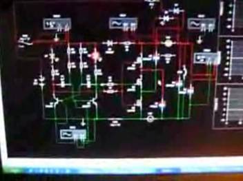
An
electronic simulation of
the circuit
done by Fausto
Quote- My simulation
is running by
itself
for a
good time. I can�t wait to
build
it and test it for good. plengo � end
Quote.
This may be
a problem for some to accept. However based on the reports of this
device and of other devices which have
been suppressed, this
shows that what is taught in electronics
and electricity is seriously lacking,
and currently it is only enough
to keep minds contained in a box that does not allow new innovations. So use the electronics background knowledge to build it, but not to close your mind off from the possibility of getting it working or learning something
new.
Researchers such as Nikola Tesla and Wilhelm Reich have already proven that there is allot more to learn about electricity then
is obvious. There is
more than one kind of electricity
and it also goes at different speeds.
Electrons themselves move very slow,
electricity moves fast. The theory behind the Tesla switch circuit is that
when the switch is closed it takes
a certain
amount of time for
the electrons
to respond and the current to flow etc, and before it can respond the circuit is changed again. So one
type of electrical phenomenon is utilized and another one is suppressed. You won't find this information in any electronics class at all. They
are anomalies that got voted
out of the theoretical systems
because the complicated things too
much,
sad
part is these
may have opened the door to Free
energy, ether etc etc.
It is first logical
to assume that devices can be configured as open systems to receive additional energy from the environment
and allow them to perform with a co
efficiency of more than one. The theory of such an operation
as it relates to this device will be discussed in
detail
in
the faculty section. This document will also
be updated with ongoing replication tests done by Panacea-BOCAF and other open source engineers.
More theories
of the operation of this device
will
be covered below
in the faculty section.
Another Tesla switch report states
that the http://www.electrodyne-corp.com/ was able to run a load more efficiently
then as normally would of normally been possible in case of connecting
the batteries.
More discussion and detail
on
this has been included
in the faculty
section. It is
important to realize
that the Ron Brandt Switch, (maybe Tesla
inspired), originally did
not work with solid
state switching.
This
was collaboration
between
Mueller, Bedini
et al. John
Bedini
did get a solid
state version
going
- cigar box job. If you search,
I think you will find that
he found the exercise very frustrating,
because, the circuit had to be thoroughly tuned - down to the lengths of wire. Could you imagine
the calculations involved in that?
And then, here
was a simple arrangement from Ron Brandt running his car around town,
recklessly avoiding the tuning problem, with its
"chattering" relays and no
tuning. THIS report suggests
that in this electronics instance,
solid state has its
limitations.
In the early
days of discreet solid state circuitry, one engineer reports that he worked with
a company that manufactured large desktop calculators. From his memory, the gates operated at
12 volts cut
off. However, these were early
days and
we also incorporated
valves
for
certain functions.
To get
a sharp
straight
leading edge pulse, the
system used a two step voltage. The
pulse would see 150 volts but the gates
would cut in at 12 volts. Hence, a
nice
clean sharp leading edge. Excellent
cut off
at 12 volts. The
engineer in question is not saying
that this Tesla Switch
system needs
dual
voltage. What he is saying is that it is the pulse that is the important
concept to understand to
drive the recharging.
Replication
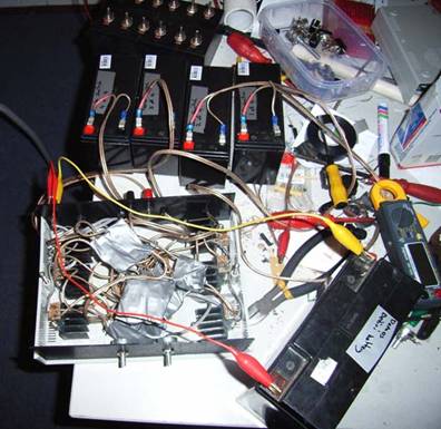
Panacea�s
solid
state version
The above solid state replication was
done by Panacea. This solid state version
was modeled off the schematic from the Eike Muller report.
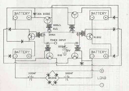
Schematic
taken
from the Eike
Muller report
We were not successful with our attempt. We wish to emphasize that is not our intent to
discourage people from trying this version due to our failure to get THIS circuit working. Our failure could be as
a result from any number of reasons. Please experiment with it to learn the circuit.
New
information as
to WHY
this version could of failed has
been included in below.
What we do wish to emphasize is that we may need to replicate
the mechanical version to understand the effects
FIRST before learning
how to do this in a solid state version.
We are basing this
reasoning on a report Panacea received from an open source engineer who has been able to build a mechanical
version. Matthew
Jones was able to free wheel his motor and charge the batteries.
This
is the most successful replication results
we have seen to date. Also many more are of the opinion that the mechanical
switching is the key. Also the
mechanical switching meets two of the three requirements
listed by Peter Lindermann
as the needed for proper function of the circuit:
1) Abrupt switching
2) Electron current blocking
Also for the needed impedance matching and balancing, the simplicity of the mechanical
reduces the number
of variables. A mechanical
switching arrangement is an element
common among other so-called free energy
motors like the "EV Gray Motor"
and
the "Adams Motor".
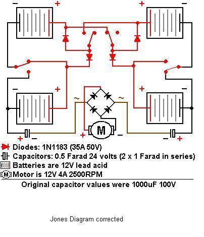
Matthew Jones Tesla Switch
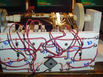
Matt�s Tesla Switch
My newest
system is charging batteries. - Matt
So far Matt has achieved the best results
that we know of. Here you can see the video of Matt�s set up which as he reports maintains
battery charge and delivers power on
the shaft. To replicate this
set up you will need the following:
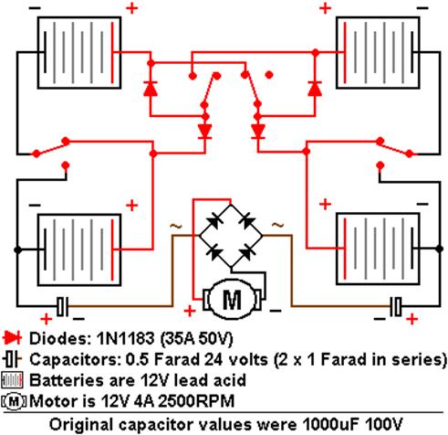
12 volt motor,
0 -
4 amps,
2500 RPMS
the Diodes and
bridge are 1n1183
The capacitors are 24 volt .5 farad stereo capacitors,
100volt do not work with anything higher than about.3 amp, so Matt had to switch. Matt is switching 160 hertz 4 times per rotation of the motor. So that means each back
of batteries goes from series to parallel 2
times. So if you�re going to duplicate this exact set up that�s
what you want use. For the
shaft Matt used some OAK circles
bolted onto a piece of all thread. Then
Matt lay copper over the oak and
nailed and glued it. Anything along these lines
will work.
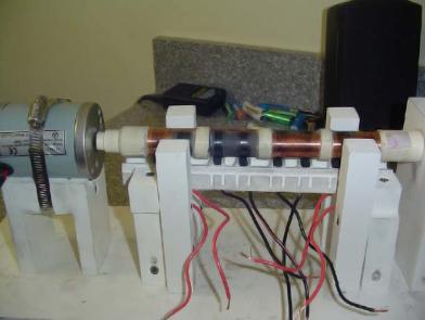
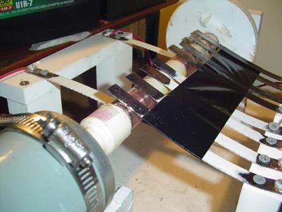
View of Matt�s mechanical Tesla
Switch
Matt states - The first tests with 24volt didn't
look to good. So I
got 12
volt motor and
I am going to switch
back.
I believe the problem is the
24volt
arcs too much, sending current to ground
if the timing is to
close. Plus putting
the batteries in
series has
some weird effect on the
charging. One battery will get
suck down and the
other will get over charged
and dissipate
anything coming into it. I
don't know why.-End
Matt has his own theory to the operation
of this device
this
is included in the faculty
section
below. Experimental
suggestions to
improve this device
include using
inductance in the setup to resonate with. Wind an inductor
that resonates at his Hertz.
This will be a lot like Tesla's
ozone patent. The only
real difference being the source is
a set of batteries arranged to give an offset potential rather than just shorting a regular battery to drive
the setup. Also
if you were to add a fan to
the shaft
and
power
a �toy� wind mill. Matt
states -That would
work
but you don't need
the motor attached
to the fan. You could
just use the switches on the fan. I would gear it a bit so
it switches faster than the fan
spins. If
charging is going to
take place
then it should
happen. Talk about
wind power. Essentially that would be something like a NO
mechanical load generator. If not you could
simulate it (wind) by just powering from a separate source to
see if charging happens. You could
experiment with frequency. Go up
to 200 hertz.
If it doesn't
you
could try
putting 2 north face coils
on the same flux as a load while the
switching is happening. As
long as you got OFF time you
should get radiant spikes and be able
to collect them. I know that would work for a fact. I have
done similar thing
on some of my homemade stuff. I figure
even if the switching action
doesn't charge the batteries
on the
long term I can take power off
the generator end and that
should
sustain the system. And keep the
light on :).
I am also going to switch
my brush design back to a "Finger Style". They seen to
do better that the spring loaded thing I used
this time. I'll have to use a flywheel and a brake to put mechanical load on
the motor. Or maybe I'll find another
motor to use as a generator. All
3 ten minute tests produced
energy in the battery.
Shutting the load
off
between cycles is
defiantly a key element. As for testing
the results; the
best
test
is timed discharge thru lump resistance or lamps. The voltage doesn't necessarily show that its working... it could
be surface
charge and
loading
the banks will show if that�s
true
in short order typically.
I'm not sure how 4 banks of 24 volts of
batteries would be laid out
to work as a Tesla switch.
Typically it would be two 12volt
cells in series and two 12volt cells in parallel. The
negatives would be commoned from the series and parallel stacks. The load then
would go between the positive poles of the two stacks and thats where the
voltage offset is at.
The voltage on the parallel stack
would increase while the voltage
on the series stack would
decrease.
This could be
emulated in
taking from
one battery into two cap�s that are
laid in
series
first, then disconnecting the single battery
from the 2 caps, reconfiguring the two caps
in series and then shorting
the series caps back into the one battery that initially charged
them in parallel just one of many
possibilities.
This schematic is a duplication of a schematic that
was supposed to have been drawn by Tesla
and given to Ron Cole. Ron Cole in turn gave
it to John Bedini
and others. What I have done is started
switching (32 time a second) them from series to parallel rapidly. One bank will be in series and one bank will be in Parallel, given the position
of the cam shaft. They
will always be opposite of each
other. The reason I have 24volt
banks is due to the
fact I
have
a 24 volt motor. What
you
describe as
typical only
applies if you need 12 volt for a load.
2, 24volt banks
in series give 48volt.
Then On the parallel side
i have 24volt. It�s the difference in the potential
of 24volt. So I can power a 24volt load
now. I also do not use the positive
poles. They are used for
switching. My load is
run off the ground side of the batteries as outlined in the above
schematic.
It hard to
look at the voltages on the batteries
because of the switching. Depending on the meter (mine
are old) they only sample at given times. With
the rapid switching it
takes
about
5 minute for the loading up
to start showing itself
on the
meters the way
I hooked them up. Initially you see a load on the
battery then the voltages start to climb. In previous version of the tesla
switch (12 volt system)
I had running for some time the voltages
on the battery would climb to 16volt per battery watching it in real time. Over all though the system lost energy in the long run
if you
measured the batteries before and after each
run.
I can measure the system while it NOT running,
then run it, and measure the system again
after
some rest time, but that
cannot provide me with the
correct data to calculate
COP of my batteries. One thing you got remember In a ONE way system
like you describe, You could calculate COP
based the Voltage
and
Amperage used outer one bank
and
put into the other.
But IN
system in which all the batteries
charge this same way of
measuring, in
all
is not valid (I think).
In this case we are not looking at the mechanical load which we use. That is easy,
if the
24volt motor is pulling 2 amps over an hour I produced 48 watts hours of
shaft energy. If the batteries
didn't lose any current during this, I have infinite COP similar to
a solar panel or an Hydro Electric dam. BUT.... What is
the COP of the
I need to know the COP of the battery because this is where the charge take effect. I am
passing current back and forth. Of course
I have loss in the system and I am
using current. But how much if any is
the battery making, or reabsorbing. I hope
you�re following me.
The circuit is a novel one. In most cases free energy
device transfer energy from one side
to another. Anything
gained is considered free. It�s easy to find. I also
want to document some load cycles, but
I am
not real sure how to present the data.
I can
build things fairly easily, I
just
have a hard time
thinking up
the Bookwork to prove
by the numbers they work. I also don't know what I should
pay attention to during testing.
Advice on Matt�s replication by open source engineer Gene
The circuit is another iteration of the MANY iterations of a Tesla switch type
layout. Lots
of ways to make the potential relative. I
see why you are using
4 x 24volt stacks now that
you explained you need a 24volt offset for
the system to drive the 24volt
motor which rotates
the cam. Switching on
the
positive poles or the negative poles is arbitrary...
Ur right that
the Cole circuit switches
on negatives, maybe there is
a benefit to this, I'm not
sure as I've not spent time messing with
it.
In a battery the positive plate
accrues
matter to go dead...
the negative plate gives up
matter to go dead.
Perhaps the switching on the negative plates
keeps the matter that�s being given up
to constantly replace the negative
terminal at the lower relative
potential. Can you do anything other in parallel, like run a
lamp or whatnot? Is there any usefulness to just transferring power back and forth between the battery stacks when you note you
are still seeing an overall drain on the system?
In addition to your COP
question on the
batteries, I'd think
that a simple set
load test with a resistor
to allow the batteries to discharge
at their C20 after you've
charged
them should let you
have an idea of if the
charge
is real, or
if its surface
charge. If you're not familiar with what the
C20 is... it�s the amount of
current that can be drawn
from the cells
over
20 hours of use...
like a 7Ah cell
would
find
its C20 by doing
7Ah/20hours=.35amps...
or thereabouts. might be better to shave
like 50mA off that and call
it 300mA
for
20 hours of use. Then you
find
the resistor that
you
can short
the battery thru that
allows
for
this
draw for that 20
hour load time and see
if you
get better performance with test after test.
Tesla is doing one thing that
you
are still not doing... and that is
pumping the charge
thru a primary at its tuned resonant frequency...
this is what allows you
to use the full source volts/amps but since its driven at resonance there is
really no current consumption and this
current consumption is what makes
a battery dead... the volts
aren't consumed... they are leveled by
the exchange of matter
from the two plates via an internal
current in the battery and an
external current thru the "working circuit."
One thing you'll note from Coles and then JB's
iterations of that device is that there are audio transformers interspersed. no doubt he is driving those audio trafos at their resonant frequency.
In reply to your counter-question
of "how much does it cost me for
1hp?" are you asking in terms of
watts
being the 768 watt figure? Or in terms
of shaft
torque? I really
doubt
you're
getting 1hp from the little 24volt motor but
you
could certainly verify that with
a prony
brake test. I'm not sure what
"10 volts left to play
with" means...
You note the motor takes
less than 2amps to
run...
how many amps
are being drawn in parallel to the
"other" load? What�s the cumulative value? The current is what relates the watts as you've already noted
that you're using 24volts
as the
potential offset... not sure
how 10
volts left fits into that
picture.
The negative
plate thing is the basic and simple understanding of how a battery "goes dead". If you snag a battery book it will explain it to you.
Bottled energy is a
decent book in this regard. This talk of divergent and non-divergent energy is not
a simple conversation to have.
Do you
know what Divergent and non-divergent
means?
Are you familiar with
the poynting vector?
It
is good you've
read beardens book. How do you load test
the batteries?
I have a custom controller
I built that sort of does what you're mechanical iteration does... tho
at frequencies in excess of 1khz... I can let it bounce charge back and forth
between just 2 batteries, 12 volts each... I can tweak it to cause one to gain
more charge while the other loses charge or I can balance it so that
they both read out at about the
same volts... at which point it
seems to slowly gain
charge
on both... It
serves
no useful purpose as once I load
it both batteries sink in
charge.
(then again these are just 2
x 7Ah 12volt gel cells... and I'm
running the charge thru
a trafo that will take
a full
7amp pulse... far in excess
of the 350mA
that should be
drawn.
The simple understanding of what Bedini does is he applies high
voltage near-current less pulses to batteries
plates to cause them to draw from the
electrolyte the currents to plate the two plates in each of the 6 cells
in the 12volt WET lead acid battery.
He applies these pulses in
varying degree...
from higher current lower voltage lower
frequency pulses from
3-15hz... to high frequency
low current pulses at higher
voltages at the normal
SG range of
250-350hz... this usually
without the 555
to decrease the discharge
impulse frequency. As applied to the Tesla switch, he doesn't
do this with straight
wires...he uses inductors...
One other
book you should look at since you're sort
of going at
stuff
Bedini did 15
years
ago is the "free energy
generation" book put out by cheniere press. Bedini had a single battery
driving a DC motor turning
a flywheel with
custom
axial
flux rotor on the far
end that kept his ONE
source battery
charged... however it wasn't
good for anything
else...
(tho perhaps it could have been with multiple axial or radial
perm magnet rotors tied to the same axle.)
There are multiple methods of generating voltages to fill
caps... The same "Tesla
switch" can be applied to semiconductors...
I know
as I've done it. ;)
All
things are relative.
Matts� response
I can usually
pull an extra load off the rectifier on the 24v system I have about 10 volts left
to play with. I usually
don't
load any higher than what
the meter shows me while
the system is running because
the motor starts to
slow down and more loss occurs. The first 3 machine
I built defiantly lost
both
in the power side of
the circuit and the motor was
not strong. The 4th one actually
charged the batteries but was built
like crap and had a short life.
That�s the
one you guys
have seen in the video. I
have sent Ash further video of
the latest build.
The loss in it (My 5th
one). Is minimum.
a one hour run cost the battery voltage to
drop
.01 - .04
over
*8 batteries. Some hold steady
other
lose just a .01 - .02 volt
off the
overall.
I could sneeze and the battery might lose that much. The speed
on the motor are maxed out.
The amp
draw is 2 amps or
less,
The motor
could run no faster. I
could increase the mechanical load though. Maybe add a
generator for greater production.
I have notice though that the batteries that hold
true,
have a good charge in them.
. Right
now as matter fact I have
the batteries charging. I'm
going to see the effect of that. As far as the negative plate thing, I
really don't
have solid understanding of
what you�re talking about.
To make it simple I see the non divergent energy flowing back into
the battery, after its been discharged and shut
off. The non divergent energy gets
crunched between the incoming energy and the Ion build up. This
should put stress on the plates and give useful energy back to the system.
I believe this based
on what
I have
read in "Energy from the vacuum", TE
Bearden, chapter
5 page
264 "Evoking the Initial Bedini
Negative resistor effect". He explains all that stuff and basically my
explanation is how I see it working.
I can load test all the batteries.
They are solid when they finally
settle down from charging off the machine.
I just know I can make motor turn without CONSUMING
electricity from
the batteries.
I have done it 6 times now in different setups on the bench. I only
know what I expect to see from the Meter and The
Scope, and if that is achieved I'm
gold.
The Tesla switch is a
bit different but
achieves
the goals. It also might be a little
cheaper than some of the others. The
next build will incorporate a
generator for mechanical load from the shaft, to show how much FREE ENERGY I can produce on a certain scale.
Updated observations by Nick
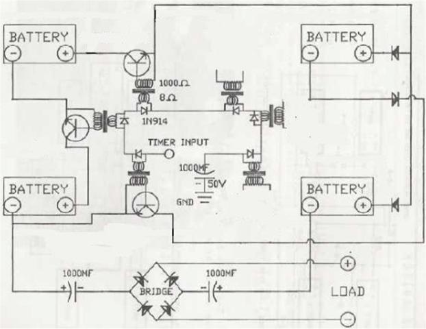
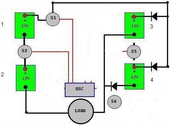
This is the Eike
Muller Report circuit design used by Panacea which does
NOT send the charging current of 2 batteries
through the load when in parallel, which ever 2 they may be at the time.
Instead, it only sends one of the batteries recharge
current through the load. A few lines representing
the positive half cycle from the oscillator
have been erased for clarity.
This schematic seems to be modeled after the Bedini web page diagram which has a similar situation.
This is the original
diagram
from the Bedini
reference
page.
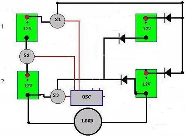
One half cycle shown for ease of viewing. Assuming S1 and S2 work together to
put batteries 1 and
Here, S6 is re-inserted in place of the remaining
diode for the opposite return path. S6 should operate at the same time as S1 and S2. S6 is also relocated
along the battery 4 short circuit path to
allow all return current paths to always
reach B2 or B4.
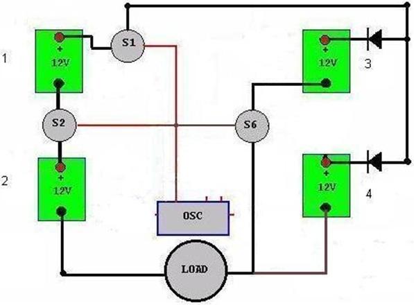
Here, S1
and
S2
close at the same time,
placing batteries 1
and
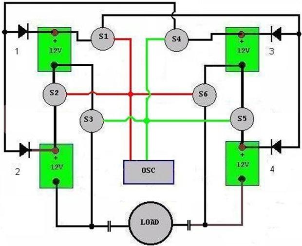
Here is the completed symmetrical system.
Note the oscillator has 2 opposing outputs shown in red
and green. Also, the capacitors are shown here, but the rectifier is not shown. (for use with a DC
load)
It is important
to understand S2 and S3
should NEVER be both closed at the
same time as this would create a
direct
short circuit across
battery 2.
The same holds
true for S5 and S6 concerning battery 4. Although the oscillator
should have two opposing outputs, it is possible to accidentally
create this short circuit
situation if
one output is not fully
shut off before the other output is
activated. Additionally,
this short circuit situation
can happen
when
insufficient shut-off
time is
allowed for the switching devices, whether it
be relay contacts or transistors.
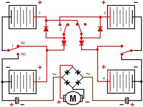
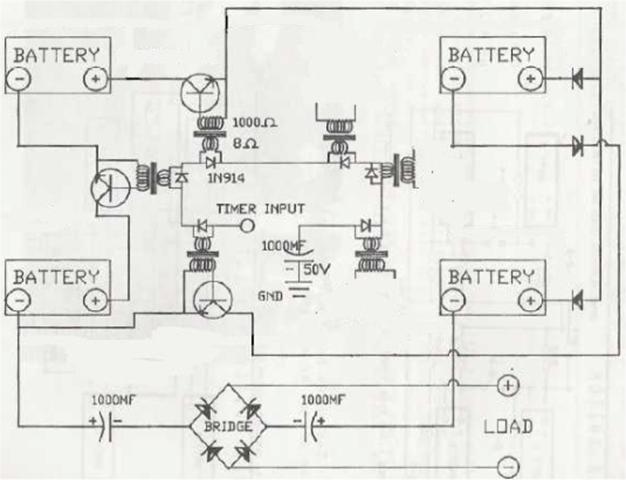
This is the same diagram I just re-created. This however is found on the Overunity.com discussion board. This circuit forces the current from both parallel batteries through the load. This is the same as the Matt Jones Diagram
This is the Matt Jones
diagram.
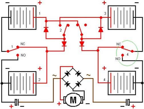
This
is the same circuit as the
bitmap
diagram
modifications I�ve made,
as well as the Overunity.com discussion board
diagram. This circuit
should work better than the Eike Muller report diagram used by Panacea because this allows
both batteries in parallel to take charge through the load. Panacea claimed no success in replication but Matt Jones does claim
success. This is a better circuit.
Interestingly, Matt
Jones
complained of one battery
not charging and the other
overheating. There is
a mistake in this diagram
circled in green. Relay 4 needs to be in opposition to relay
1. Instead, his diagram has relays
1 and
Here is the Panacea circuit diagram modified
to contain same oscillator circuit but with a different switching
scenario. This matches
the diagram on the
Overunity.com discussion
board, the schematic diagram re-work
here as well as the Matt Jones diagram (less the oscillator).
Note, the control circuit has 2 control diodes and corresponding transistors
re-wired. If Matt Jones is
capable
of making his
circuit
work
with mechanical
switching, this
would
be the transistor equivalent.
Tesla switch by Fausto
The following
is a chronology of
circuit
ideas, tests and events done by
Fausto�s.
In this version he has used a hybrid of John Bedini�s circuit ideas and combined them with the
Tesla switch.
Simplified circuit
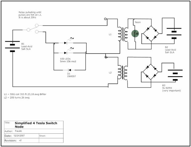
I have been
playing with this 4 N.Tesla Switch for a little awhile. This circuit is as
simples as it can be. 2 coils
and a
switch.
The switch is flipping I think at about 10 pulses
per second max, may a little bit less (see the video) and the battery has been
delivering a good current for hours and when it is finished. I switch the
batteries and off it goes
again. Frequency is 16ms pulses (50% duty cycle).It is standing
a very long time compared
to some load tests I
have
done
when I playing with SSG (Bedini motor)
and I never had it running and
giving so much power out for so long.
I really think the sudden cut off
the current is THE trick.
It continues running 2 batteries for 4 days now. They
are much depleted but still giving
up 100m of power, very impressive. Proof of concepts
Part 4 for N. Tesla 4 Switch device.
- Video is here
Some observations that that I have:
- The
batteries are depleting in this one node setup, but, they are never depleted totally. It
is always producing enough energy
back to run it again
and generate
watts
for hours
and days.
- Faster switching is not necessarily the best. What seems to matter is that the destination battery
gets some HV pulses and the source battery IS drained so that it allows the charges
to move or better,
to resonate.
- Impedance
matching is very important, without it the source battery only drains very fast.
- There
is a difference in the kind of
electricity that is collected on
my B3 and B2 (see drawing above) and the using a
capacitor at B3 does not work as
well as using a NIMH. B3 will have a
"ghost" voltage
but that voltage is changing the dynamics of the whole circuit.
- Switching the batteries back and
forth FASTER is better.
- Having frequency pulsing IS important. So there are two things here:
pulsing and switching the batteries or source of current.
- 4+ days now and still generating power with almost depleted
batteries (technically they ARE depleted).
- The
high voltage seems to be the same when B1 is
giving
12v or 2v Very strange.
- The
voltages between B1 and B2 will be balancing each
other. So starting with a higher voltage in one and lower in another will first cause a fast balancing and them you will be able to see
some of the effects above.
- The residual voltages I have now are consistent with the drop
voltage of the LEDs
(load). Hmmm.
I can barely
wait to start testing with
3 batteries (2 nodes).
But here is the quickies:
315ft
of 23awg and 18awg. Grab
both at the same time and
just go around a spool 1" in diameter
until the whole 315ft is gone. You have to pay special attention to the direction of
winding it so look at the yahoo
group and read
carefully. But there is no secret
really. If you hold with your left hand
the spool just wind it towards down,
from your face (you looking at the
spool) towards your feet or down using your right hand. Go on turning the wire and making sure they are close as possible with no gaps in
between. Now ask your wife/girlfriend to bring the beer and sip it in
your mouth before you die of
boredom because 315ft
is about
2000
turns!
I only
remember having those strong feelings about something when
I was living in
Up and downs
of life. Well. I used to that. Now back
to work.
The 3 batteries switch
is simply phenomenal. It was working very well until it simply
died
and died fast. So I
decided to recharge
all the batteries using my
SSG and
try another test
with all at the same
level, instead of how I
had it. One fully
charged and the other 2 half
so.
In the process of charging the batteries I had an idea, why not use my SSG as the load, which is a much more efficient way to charge another battery instead
of what I was doing with
one coil
that was going crazy
with all that AC (magnetic field collapsing and before
even finished here came another
current to create another field, but ops,
this time inverted and
so forth).
With the SSG as the load a few things I could notice
already on the beginning of the test:
1 - It adjusts itself as a load to the 3
bat switch. Its impedance changes as the charging battery changes and therefore the "load" seen by the "tesla switch" changes. That's absolutely great.
2 - SSG is
charging a fourth battery much
more efficiently than I could ever want.
3 - The
3 batteries are behaving a little
bit different now, since all are charged almost to full capacity,
but with
different impedance for
the load, they are much more stable in their voltages holding
4 - It seems that one of the batteries
of the 3 is actually charging!!! (Time will tell).
Video Here - Now trying out the 3 battery switch feeding my, guess
what, SSG. Let's see if
it will charge up a battery as it runs the other 3 will
it be self sustaining?
My
3 batteries switch is running now for more than 24 hours and I already outputted about 20watts of power out of
those 3 batteries plus another one that has being charged by the SSG machine that is used as a load on the 3 batteries
switch.
I also tried today closing
the loop, connecting not only one battery
to the SSG but also
another output from the same SSG back to one of the 3 batteries on the switch system. It is working wonderfully. The
wheel
is
spinning at about 600rpm and everything seems to be (after switching
back and forth the
batteries) at
stable voltages. Output increased
to 12v and 200ma
and fluctuates
at min
6.5v
and 60ma up to 16v
and 500ma.
I think I already ran the power that was available
on these batteries a long time ago and
that
is based on previous
load tests I have been doing because of the SSG project
(SSG = Simplified School Girl motor from Bedini). Closing the loop seems to work well because
the batteries
are on and off by the
switch
plus the 22000uf caps
that is decoupling things a bit.
I have to tell you, this thing is working at least very efficiently. Time
will tell. I think
if it runs without having to recharge any of the batteries for
a week this is most definitely a
super
efficient device. I can�t
wait
to try the 4 batteries switch,
but one step at the time with
lots of testing in between.
I am also collecting all the output into
the computer and running calculations
based
on the data. It is not
super
good
data
because of the speed of sampling but it is good enough for this
preliminary tests. �End Fausto�s
technical discussion thread link is posted under
the �technical
discussion section�
below. Fausto�s videos channel.
Experimental solid state switching
The following is
courtesy of Jetijs
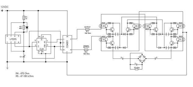
Solid state
by Jetijs
� Down load
The following is courtesy of Dave
Solid state by Dave Jpeg � Download
Solid state by Dave PCB � Download
Solid_State_PWM_by_Dave

|
Transistor choice regarding experimentation of the solid state version
Most do not recommend 2n3055's.
Two
well rated transistors you might
like to try are:-
KSE13009 NPN 300V 12A From Fairchild, and MJE13009 NPN
400V
12A from ON semiconductors- Might
be a bit more expensive. Or A choice of
or mjl 21194.
Automatic battery switching
Experimental ideas- Take a look at these specs. They
have ac & dc control, in particular the D1D40 (dc) and
the EZ240D18 (ac)
models-
PDF Link.
The DC one
could be tried in
a Bedini
technology. The max
turn-on time is 100 microseconds
and max turnoff time is 1 millisecond.
With coil and/or pot
adjustment, this will replace
the transistor in the
Bedini SSG. These could also be used in the
Tesla Switch configurations
for automatic
battery swapping. Turn on voltage of
the of
3.5 volts and
turn-off voltage of 1
volt with a control voltage range of
3.5 to 35 volts
give
a wide swing of source voltage as well.
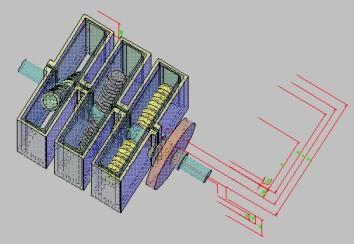
Tesla Switch - Geovoltaic Energy Pump (GVEP)
The following information has been
archived form the Peswiki web site as a backup.
Please visit
this
page for the original version.
The GVEP consists of a Tesla
Switch
utilizing a
rotary mechanical contactor in lieu of solid state
components to control cross charging among a standard residential battery bank of 12v lead-acid deep cycle batteries, arranged in groups
of four. An enhanced version of the Energy Machine of Joseph
Newman, herein, the "Newmach
Module(s)", is/are used to drive the rotary mechanism, with the
Newman
Commutator
and Tesla
Switch
sharing a common contactor disk assembly. This choice not only
provides a suitable motor to rotate
the disk which consumes virtually
no power to drive it (nanoamps), but also contributes a positive back pulse of high voltage
at
the switching frequencies
of the battery array, which is additive
to the overall energy
balance of the system. Unlike other
possible drivers for a rotary contactor, the Newmach
Modules can be made compact, with a minimum of moving parts, are not encumbered by
patent rights
(disclosed and published in-depth
in 1984, its
1983
PCT patent expiring in
2000),
and can be substantially improved over its nominal observed and
replicated level
of performance.
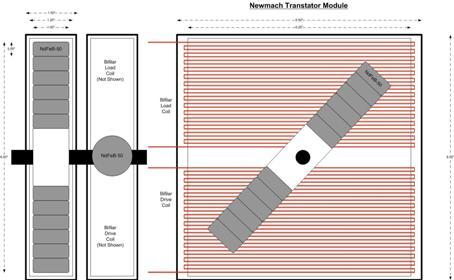
GVEP Commutation
System
Based on Joseph Newman's expired 1983
PTC Patent WO8300963 (Figure 6), the proposed Newman Modules are
enhanced over the stock Newman design in four important
ways. [1] A new
generation of Neodymium-Iron-Born (NdFeB) magnets
are to be utilized, [N-50 Class, Ni-Cu-Ni clad, Remanance
1400
- 1450 (BrmT), Max.
Energy Product
48
- 51 (BH)max(MGO),
Coercive Force ≥10.0 Hcb (KOe), Intrinsic Coercive Force ≥11 Hci
(KOe), as
described in the paper "Motor Design Advancements
Using
NdFeB Magnets" [2] In the book "Manual of Free Energy Devices and Systems" by D.A. Kelly (1991),
Electrodyne
Corporation reports that Tinned
Copper Wire produces a 3x
improvement in magnetic field
strength
when used in Newman coils, over regular copper wire. [3] A
ferric steel keeper will be employed, to concentrate magnetic flux, resulting in a 3x performance improvement, as demonstrated by Lindemann in the lecture ["Electric Motor
Secrets"]. [4] The use of Bifilar wire will increase the energy release per pulse by a factor
of 250,000x, as per Tesla
While Newman has spent the past decade re-engineering
his system to reduce the Back EMF negative current spikes in favor of more
mechanical energy, resulting in a completely different
machine configuration, the Institute
believes that his device was far more valuable
in its
original embodiment,
when
in a
context
which permits those spikes to be properly utilized,
as presented here.
While a large Newman Energy Machine, which itself
puts out all of the power necessary for an average
home, will generate back spikes so powerful that they will destroy conventional batteries, when integrated as
the driver mechanism for a Tesla Switch, and scaled down to simply
drive the rotary switch mechanism,
the spikes are of a reasonable magnitude which
complements the self--charging
operation of the battery array. Moreover,
these "negative current"
pulses (which are actually
positive {+} polarity, or rather,
a 'current of holes'), must
be matched with an electron
source in order to generate the conventional current flow that provide a useful charge to the battery bank. In the GVEP, much
smaller Newman devices are used, which
are far more efficient,
and are properly
integrated with home-scale battery
infrastructure.
Newmach Driver/Amplifier Module
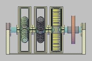
GVEP w/ Newmach Transtators
The Tesla Switch creates a pulsed current flow between four 12v, Lead-acid
batteries in an array (in the anticipated system, three such arrays operate together, or 12 batteries in all). Through some mechanism of radiant energy entrainment, net energy is captured
within the battery system in this process.
The rate of entrainment charging
adjusts itself to the external load being drawn from the batteries; the greater the discharge to load,
the faster external energy is captured from the active vacuum. The switching rate also
determines the rate of charge,
and must be kept in a range (20cps to 800cps, TBD) which, in relation to the [then] load, does not damage the batteries from excessive
charge.
Those who have been involved with FE/OU experiments have consistently
reported that in various
radiant energy devices,
electromechanical switching yields
superior results to solid state electronics. When using
solid state components, PNP transistors are widely preferred over NPN transistors, however,
the reason for this has only recently
become apparent: atmospheric electrons
from the local environment can enter
the circuit in a PNP device, but not through an NPN. A picture emerges that radiant currents do not behave in the
same manner as electron currents. Dr.
Lindemann recommends beginning with mechanical contacts to eliminate sources of error, before taking a FE/OU system
to a solid state architecture. In
the documentary "Energy from the Vacuum", Part 2,
Bedini himself features a "transistor-free" version of his motor, which is the one he says 'will run forever', while Stan Meyer
filed U.S. Patent 4,613,779, on an Electric
Pulse
Generator to be used
with his Water
Fuel Cell, with the following Background:
"Power supplies for electrical systems
have
been utilized for a
century
or so. As time
progressed new uses of electrical systems
placed a need for more sophisticated systems. One particular
utilization is the need for power
transfer
to the utilization
device but yet with the requirement that there be power isolation. The advancement of electronics
and power devices such as SCRs, Triacs and the such, appeared to be
an
obvious solution to such
a power transfer. Current limiting circuits also were developed. Unfortunately, the
solution was not met. The electronic devices in most instances could not limit or tolerate high power. Finally, it became
apparent that the electrical systems, with
this type of current limiting requirement necessitated
electrical power supplies--not electronic."
Current Source-A limitation inherent
in most FE/OU devices is that the
radiant energy extracted from
the quantum vacuum ("ZPE") comes in the form of potential,
and while this can flow
as a 'radiant current',
is not sensible as an electron
current with ammeter instrumentation.
If the system does not carefully match this potential to an
'electron source', high
potential will build, which destroys
batteries and blows capacitors, rather than charging them.
Failure to account for
this
stumbling
block has been the Achilles' heel of many otherwise viable
free energy devices. The H2earth Institute has determined, for
example, that
the Meyer Water Fuel
Cell's
Electron
Extraction Circuit
is actually an "Electron Donor"
within the radiant FE/OU circuit that runs
the device. Since the WFC itself, properly configured,
consumes no current (it is a water capacitor that likes to be 'blown', repeatedly), the WFC/EEC
can serve to provide current within an overall fixed-facilities, distributed generation
context. However, because this raises issues - at the household level - of what to do with the large amounts of [then] surplus Hydroxy gas which would
be produced, a
residential
radiant
power system would
best utilize environmental free electron sources, particularly Ground and Air. For this, the Tesla
Balance-of-System Components- The
objective of
this
project is to design/build/test
a version of the Tesla Switch which can interoperate
with the large range of commercial,
off-the-shelf residential battery
bank infrastructure which
has hit the market in the past
15 years to accommodate the conventional Renewable Energy marketplace. Tens of thousands of
homes now have 12v battery
bank systems for home power, charged
by Solar Photovoltaic panels, Wind
Turbines, Micro-Hydro, and Biogas energy sources. The
Application -We
believe that local Renewable Energy
Contractors are a pragmatic and innovative group of engineers, who will find a single FE/OU powered test house to be sufficiently
persuasive to
begin
testing, using, selling, and installing
the GVEP themselves in their local communities. Each working home
power installation will then
attract its own converts, as friends and neighbors of "early-adopters"
also opt to become energy
independent. Due to the electrical and mechanical simplicity of the unit, no significant investment
is needed
in fabrication or
assembly to begin
producing such
systems.
With
no big factory,
precision
machine
tooling,
specialized manufacturing equipment, or
venture
capital necessary, and no issues as to intellectual
property rights, the GVEP can be productized by dozens of independent small business startup ventures around the world
simultaneously, and bootstrapped by
each of them into substantial sales volumes.
Working hardware, locally demonstrated and available for immediate purchase and installation, trumps
any
skepticism that fundamentalist
scientific dogma can throw
at it. The
fulcrum that
gives a mainstream
establishment leverage
to intercept and block
successful FE/OU technology has been - virtually
always and everywhere - the point at
which the Inventor Turns Entrepreneur. First,
there are psycho-social factors
common to talented research inventors,
which reciprocally make them unlikely "people persons"
to organize and lead venture teams (i.e. "they don't play well with
others"). Invariably, Inventor ego, paranoia, greed, suspicion,
and poor socialization/communications skills, or bad judgment (or bad
luck) in
finding/selecting
potential
partners and
team members, inhibits successful commercialization
of
the completed technology. Second, however, when the development
stage technology venture turns to venture capitalists and investment bankers
to underwrite productization and manufacturing,
these institutional investors always must
obtain independent
technical evaluations
from respected mainstream academic university research professors. They must, for reasons of legal liability,
conduct this "Due Diligence"
investigation, soliciting
the opinions
of independent scientific
sources. Of course, for reasons
obvious, establishment scientists
will - always and everywhere - fail
to endorse FE/OU technology concepts, thus dissuading
the venture capitalist or investment banker from backing the inventor's technology, product, and venture. The
GVEP, requiring no such financial underwriting,
and having no one aberrant inventor,
can easily sidestep these impediments, sliding into the marketplace
where no opposition can effectively
prevent it.
Project Status-The GVEP
has never been built before. It is a logical integration of
complementary technologies, each of which has been independently
demonstrated and is in the public
domain. For various reasons which the different components exhibit, they all should fit together in a very organic, symbiotic manner.
The H2earth
Institute has arranged for the promulgation of a comprehensive Engineering
Package of
detailed
drawings and specifications
from its volunteer
Research Associates, which
will include a
set of electromechanical assembly drawings in AutoCAD,
specific circuit
schematics in
pSpice,
and 3-D modeling animation in
Maya.
This documentation
is
expected
to be
completed in the
4th
Quarter 2007.
An Institute
team in
Two 'Residential Systems Testbeds' have been arranged, with test houses donated both on Florida's Space Coast and
in the Tampa Bay area, at which full scale home power systems utilizing the
GVEP and conventional
battery banks will be installed
for evaluation and demonstration
purposes.
Nomenclature- The phrase "Geovoltaic Energy Pump" is an
effort to normalize the concept to Bearden's Geothermal Heat Pump analogy for FE/OU systems, and the Solar Photovoltaic
industry that it will leverage off of for the balance-of-system
components.
Geovoltaic Energy Pump (GVEP)-Down
load high Quality
Faculty information
Ongoing experiments
Tesla switch by mondrasek
http://www.overunity.com/index.php?topic=1645.80
The Tesla switch as featured in the practical
guide to free energy
The electrodyne report that
was used in the Practical guide to free energy
(PGFE)
stated that they had to add energy to the system on a regular
basis. They also used the
6 switch version.
The original circuit was a
4 switch,
according to the PGFE.
With
4 switches� it is not possible to have
a grounded circuit which is what would be required for the
solid
state version. No
one has
ever
came out and said it on
this
particular circuit but if you
piece it together with the theories
and working operations of other devices, then the conclusion should be obvious.
Nikola Tesla's reports describe that
when the duration and frequency of high voltage pulses were varied, certain
effects came in effect. These included
lighting,
heating and others. Certain
researchers such as John Bedini and Tom Bearden have proposed theoretical and physical
models to suggest that by utilizing
pulse technology in certain configurations, these
pulses are able to draw energy
directly from the environment. A theory of
this related particular operation can
be found in the following guide:
http://www.free-energy-info.co.uk/Chapt5.html
Independent theories of operation
done by various open source engineers
By Matthew Jones
My
theory is pretty simple
when you look at from the aspect
of Divergent and Non Divergent
energy. A lot people don't like to look at this end of it. If you look at the Electron as a small permanent magnet you can
see how, what I am going to explain
would happen. If you look at non divergent energy as magnetic DUST (No useable mass) that also helps.
There are different opinions. I tend to agree with Bearden's theories and have actually found proof, as far
as I am concerned, on a lot them. You know
how the motor gets its power from
the Tesla Switch so I don't
have
to cover
that too much.
Basically you have a potential
between 2 potentials (Or positive poles).If you have
24volt on one
side and 12volt on the other you
then have a
12 volt potential. This is
how you to get power out of the system and still retain the energy used. Loss only comes in play from heat and natural resistance.
Your just discharging from one and charging another. The electron movement does not care how you
make it move it still creates a magnetic field around itself most
likely while its hopping from one atomic structure to the next.
The NON DIVERGENT
energy on the other hand moves
opposite the direction of the electron. The basic and simple scenario is, if the electron coming from the positive pole of the battery,
is charged to the positive (Not actually,
just for example)
then the energy attracted
to it would be negative by
nature (Dirac).
This energy will not
bond with it but collects from
the vicinity of the wire.
So
you have this
field of energy outside
the wire waiting to go into
the battery closer to the center of the charge (remember the magnet?)
So we turn on the circuit
on. The electron leaves
the battery creating a void on the crystals of the plates. The electron then travels
to the next battery. While on
its way the divergent energy collects
around the wire. We
turn the circuit off (You must
turn them OFF), taking the load off of
the battery. Everything inside stalls and we are left with vacuum
inside the battery.
Empty
Then all of sudden when all this
fluffy weak energy is flowing back into the batteries, we
slam it with a
brick
from the other direction. Instantly turning the dust into
compressed solid mass!!! WALLA!!!
Extra Energy.
Well You ask "If the dust
was charged
Negatively, then how
is the MASS that formed from
it now charged positively?"This is where things
get weird
opinions vary.
I continue
to look at the permanent magnet scenario. A little experiment I tried
some time ago got me on to this. You
take a really big magnets made
of Neodymium. Say
100lbs of pulling power. Then you take ceramic mag
5lbs grade8. Push the 2 North Pole together till they
touch. The weak magnet
will
stick to the strong one. Left
attached for some
period of time you will notice that when you take the weak magnet away from the strong one it will
continue to be attracted in the same
direction. You have
flipped the pole. It will, in
some cases (Grade5 or below)
start to repel from the opposite side. You have re polarized this magnet. The
magnets not very strong but the poles have flipped. You turned
this
magnet back into dust.
What happens in the battery
is similar. You crunch the Divergent energy together and every little tiny peice then flips poles and bonds
together with the incoming energy. I
can duplicate the opposite effect in a pulse
motor. If
you
use a
really big set of
magnets for the drive
magnets and a decent coil you can
flip the pole on the energy in the coil. When this flipped
energy leaves the coil if given
a choice to go either to ground or
to a potential it will travel to the
potential every
time.
Maybe you
have seen my simple circuit. This is how
I discovered the flipping of the crushed energy.
If
you run the motor
as a
straight motor,
it will build
up BEMF and
make a lot of heat and it won't run with alot of torque. (Not
that it has much anyway). If you run
weak magnets for the drive,
the amperage coming
in to the motor will equal the amperage leaving, minus, just a small fraction. (IE
1 amp draw, .8 charge).
Now if use a strong magnet the amperage
ratio changes dramatically. You might feed it 5 amps and only .5 amps come out. But since we know it is
recovering energy based on
the small magnet drive then it must be recovering the same energy
under a large magnet drive. So
why
the decline in
amperage?. Simple. The dust left
over,
after
the big magnets have crushed it, has no weight, it doesn't really want to flow. And it travels to the positive
pole of the charge battery, NOT the negative pole of the run battery.
If you
haven't seen the circuit hers the video
with a schematic .
http://www.youtube.com/watch?v=BnBPEPhqcI8
Now you�re probably asking why
he is babbling on about everything
under Gods green earth. I'll
come to the point. I have built 4 Tesla switches
with a motor for the load. So far I have not been able to recover
the losses in the circuit
and the motor. The device is defiantly more conservative than a conventional circuit. And I could use the shaft
power to make recovery. I believe
one of the keys to making this circuit
work and keep a charge on the battery is how well you crush the energy
coming out of the load. I
believe that if broken down you will have
more surface area for the divergent energy
to mix and bond with. At the
same time you need that hard hitting crunch that turns it all back into
compressed energy. And you don't
want to re polarize it, because that
will force the divergent that�s near
the wire away.
Now the only way I have been able to imagine this happening
with a conventional motor is based solely on the
timing and what kind of motor you
have. If you run the motor, crush the energy, then turn the motor
off and use the kinetic energy left over to turn
the motor slightly and
create charge, A good charge, and dump all that
in the battery in that order you may
start
to overcome the loss in the
circuit.
I see a better motor
being
built. Similar to
a pulse motor, but
with some properties
of a
attraction motor. The pulse to crush the energy
and an conventional to
give it a good jolt. This
something that I
have started looking
into. In addition to that
I am going to start
looking into duplicating some older motor designs. Something from the time of Tesla and Edison (
The circuit was not designed specifically for a motor. It�s meant to run any
load. But if you look at
what
they had to switch it with in
those days, either a tube or
relay
setup
to switch things or mechanical switching.
The reason I am not fond of using a transistor (Or
tubes) is the amount of
current
you
have to let go to ground, may very
well stop the non divergent energy
flow in the circuit. Unless it was done along the same lines as a Bedini
motor in which you
generate the trigger current
that gets sent to ground. Then
your back to
mechanical hybrid.
In Patrick Kellies Free Energy Guide, the older version, that discussed the
Tesla switch in some detail,
mentioned that electrodyne
ran the circuit for 3 years,
but had to add energy
to the system on several occasions. They
switched
with transistors
and relays. Grounding
anything in circuit is asking
for loss. So in testing
this
circuit
we should find
one of 2 things. Either the circuit is capable of inducing
extra energy from the vacuum or it allows us to perform work at greater duration
of time. Either is fine with me.
I believe this to be the fundamental key to
free SHAFT energy. Anybody
can build it. Some will refine it. But most all will learn from it. Hope that wasn't too
much in one letter, I felt like I had to get it all out.
END
You must consider that there are two
electricity�s at work here, the one you know
(Male) of and
the one you seek to discover (Female).There
are always 3 states at work, just
like up, down and static
or in potential - positive, negative
or none.
This may help - Jerry Bayles
'Eureka Moment' where he does explain the opposite
energy at work and the difference
between the two in his own words in
developing his theories: http://www.electrogravity.com/
Consider
the fact that the 'new' electricity you
have generated may just act
oppositely to what you would accept as being normal. Also
learn to understand that you cannot
easily measure this enrgy and the
best way is to 'palm' wires and devices to see if you can't feel a
field and look for a cooling breeze or a faint
cool brushing. Yes, metaphysics
at work here and will include your
Pineal gland to help in the decision
making
and even Dowsing.
Do you get headaches as you are working - have you ever considered that you
may have developed a torsion field that
is creating a stress in your
environment? Perhaps this may help here: http://magnetism.fateback.com/index.htm
David Lowrance's
CSSP public information site. Many devices here that illustrate opposite energy flows - inflow
and outflow -Rainmakers and Tube devices that
create torsion fields
and can utilize
'consciousness' as part of
the equation.
In other words, your actual
conscious state as being a part of that device. It is no longer
just 'electronics' - there is more to
it that has been suppressed from us
and denied to us by being urged away
from Nature and the way Nature
operates. �End
You
might look
at this way
when
you
switch the batteries potentials back and forth like that
you create a reversing voltage potential across the caps and series bridge. So in essence you have a time varying
potential. In electronics 101 you learn that caps block DC and pass AC for steady state analysis (sinusoidal ac) the ac impedance is calculated
with the standard formula. With
the Tesla switch the ac
waveform will be more like a time varying square wave. The current will pass
through the caps but it won't
likely be sinusoidal in form. More transient in nature it is interesting to note
that they take the load off the negative side of the batteries which is
where the electrons are actually flowing from
in the circuit. Also note
When a capacitor
has AC
or
From Dave-I
came up with my own by following the
actual flow of
the circuit, (I couldn't
find anything published that didn't have errors in it) it can be Tapped at either end.
The basic concept is
to put the Charge
batteries in parallel (12v)
to lower the V potential and the Source batteries in
series (24v)
to double the potential. then connect the + and the - of
both sets together with
a Load in between either
the + or - side. If you need DC
use a
FWBR or you will have
an
AC output.
As the 24v potential
goes through the circuit it will be backwards through the 12v batteries (recharging
them) it will leave you 12v
for the load. The more Amps you draw through the load the more will
flow through the batteries. Then you
switch the positions and run again.
My theory on it when set up
proper is that since the Ions in the battery travel SLOWER than the
Electrons
in the circuit when properly tuned the ions
should just
oscillate back and forth, not actually touching either
plate Pumping electrons through the circuit to
do work.
I have the switching circuit
figured
out using
6 Fets or IGBTs and NO Diodes, (for
useful
power circuit instead of toys)
have found the HEATING problem
comes from 2 of the
FETS that swap polarity when switched. I have been working on
how to set up a totally floating gate
drive
that will follow the
flow. I will
have to dig out
my notes again on this
but I think it went like this. The
FET sees a HIGH potential when turning on so it needs V+
~18v
to turn the gate full
on. Now as
soon as it turns on
it becomes LOW, so now the gate
needs to drop the +18v or it
will
burn out the Fet.
If any
of you Electronic experts have any suggestions let Panacea know and I will
go over where I'm
at with
it in more detail so
maybe we can get
this
worked into
a usable
device.-End
By V- This is
just a guess but
I think
the short is very
brief
and may be what builds
up the
current to a high level for a brief
instant before it gets jerked
the other way. So we have alternating shorts instead of alternating current. They probably
work the same way. Maybe that's why it�s good to have an inductive load. Think about what does a coil do when you
charge it up with a current and then suddenly short it?
All use of electricity
involves
a short I think because that is what completes the circuit. When you
short the battery it builds up a high current level real quick, the electrons bunch up and then are
released in a different direction. Maybe your dilemma comes from thinking
of the circuit in a static
manner when its
a dynamic function that
it works on.
From
Rob- I have tried
the TS on the Mueller visit.
Actually,
the key to all this is
Ron Brandts
relay!
I had
no luck at all with
solid
state.
I personally think that
the key is in the electrostatic
pulse.
His
old relays would
have been chattering
away.
So too will a rotary switch.
This worked for me somewhat and I charged some old batteries
up, and my son who is doing Aerospae at Monash, still refused to believe
what he saw!!!
I ran
a small
dc motor for about 5 days, till he went back to Uni,
and the batteries were still charged!!
I have not published this
as I
do not want to draw too much attention
from the
"plodheads". As
far as I am concerned this worked
because the Electrostatic pulses coming from the rotor -driven by one of those small
hobby motors are straight edged = sharp.
Also, I had a sharp cut
off /
cut in on the plate to activate
the pulse. = short
sharp
pulses. The audio transformers
might be a bit overstated
as the amplified spike is where the danger is.
I also
found
that the 3055's
are
susceptible to Spikes. The
555 circuits
did
nothing for me as
the difficulty becomes compounded
with
the amplified latency
in the total solid state circuitry. I
think bedini
also
had
this
trouble.
If you put
a pot in series with the small motor
= variable speed drive. Also, I
got the best pulses by using
the total batteries in series, for
me 48volts gave a sufficient spark. Try to irritate
the contact poit
so as to encourage the spark!! Regarding
the frequency operation of the circuit.
Bedini ran his slow.
I think
he was talking less than 50 Hz. This will
rock on up to at least
1000hz. Maybe more = too much heat. Connect the
pulse
across
negative and input terminal
as per figure T-7. Start slow and experiment.
On the input I
disconnected the 1000uf cap. One
side
of the contactor goes to the left and the other side of
the contactor goes to the
right.
As per the diodes. Also, if it
works
for
you, don't leave
it running too
long without a load
or your batteries might start cooking! It seems to pull most current with a load. If you use the variable pot across the rotary
contact breaker switch connected across the 4 batteries, that your TS will zoom along.(Untested).
By jibbguy
The idea is to have a floating "lower" potential
of a dipole source, where having a load causes more current
to flow so
it actually "charges"
and
not detracts
from the source as it "normally" would, seems to be a common reoccurring theme of Tesla and others.
Somewhere,
there is a very significant secret to unravel
here in these concepts... Like the 4
battery Tesla Switch
arrangements that are self-powered, supposedly being able to power
vehicles. In those designs, is the mechanical
switching causing
DC transient spikes, which
provide radiant energy to charge the batteries, wouldn't
seem to be enough coming from there to explain the effect.
But by
all accounts the complex Tesla switches are a bear
to get to work and supposedly only 2
people ever have. A small electrolytic filter cap, a load resister for discharging the cap, 4 clip leads, a double-pole double-throw switch,
and a small rechargeable battery,
manually charge / discharge a cap by throwing the switch to put the cap
first across the batteries then across the resistor until the battery is down to
a predetermined voltage measured to
4 significant digits.
Make sure the battery
was always charged using old-style "flat" DC so there is no
oddities of radiant charge involved to skew the data. Then do
the calculations on how much
battery charge was actually
used
to charge the cap over time; and
see if it matches a regular direct discharge across the same resistor load on
the exactly same- charged level battery. You would also have to
carefully measure the output of the discharging
cap across the resister over time;
to compare that to the batt's
loss of charge over time to measure the leakage current losses in the cap.
Maybe using two
"Integrator amplifier" circuits to measure
the "area under the
curve" would
be an easier way to measure the cap's output/discharge
and input/charge (the batt's discharge).. Integrators "adds-up" voltage
over time and output it as a representative
constantly-climbing dc level that can be simply
read by a meter or scope.
Medical research Doc's use Integrator Amps to measure total blood flow vs. time,
and the analog circuit that
does
this
is fairly easy to build using
op-amps.
The problem with
all that is of course unless you
have really amazing results (...at least a
10% gain in COP using the cap verses the
resistor), the readings and
inherent error
(probably "+/-5%" total
at best) will make it all inconclusive.
This is the big problem doing
COP measurements with batt
or cap related circuits.You'll never shut up the skeptics
quibbling over a dozen different
measurement accuracy issues let
alone anything else.
But nonetheless it would be a valuable test to do: If a cap does the same work with a lower
"cost" of charging it
verses the source doing it directly, this is "free energy", important
news,
and
basis
for further study.
The Tesla Switch is For Electricity
what the Heron Pump is For Water?
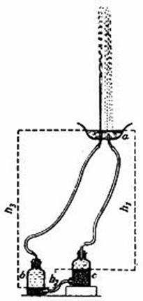
An open source engineer has a theory that the
Tesla
Switch
is near to be equal to the Heron Pump. Heron Pump was used by Egyptian�s to send water to the heights
in his buildings by converting the gravity to pressure, (like in electricity converts
amperage to potential in the switch?).
Above is a Heron Pump, when
water
is not
pumped, bottle b is interchanged by
bottle c and the match begins again.
This engineer reasons that
Tesla was inspired by this system for
create the Tesla Switch. If
inspiring us for
this we can rebuild the
Tesla switch from his
creation to get it better.
The Heron Pump
or Heron Fountain is not
an
OVERUNITY device
but it was very useful for the Egyptian civilization
and the middle Ages. The
similarities for this theory compare
the batteries electrons
which are sorted when it is charged. The electrons when in closed loop go out
in heat, when in open loop
go to another
HERON'S FOUNTAIN
The following information has
been archived from
this
site. Most of fountains that
you can see in parks are driven by
an electric water pump. But Heron, an
engineer in ancient Greek,
invented a very curious fountain.
It continues to spout water without
any pump and energy source.
Let's make Heron's fountain as shown in Fig.1, using daily
used materials, such
as plastic bottles and
plastic tubes.
Fig. 1
MATERIALS
and
TOOLS
plastic bottle(1 - 1.5l) x 3
plastic tube(inner
diameter
rubber stopper(which
fits
to the mouth of the
plastic bottle)
x 3
plastic sheet(30
x
sellotape
tripod stand with clamp
copper pipe(diameter
glass tube(diameter
METHOD-Heat the glass tube and make a nozzle as shown in Fig.2. Make two holes
(diameter
Attach the rubber
stoppers to each mouth of 3 bottles.
Cut the plastic tube into 5 pieces and connect the 3 rubberstoppers with
them as shown in Fig.5. Fill bottle C
with water and
put a
little
water in bottle B. Attach the funnel
to the tripod stand and set
bottle B,C as shown in Fig.1.
If you
pour water into the funnel,
water begins to spout out from the nozzle
continuously.
PRINCIPLE-In Fig.6, as
the water level of the funnel is higher
than that of bottle B,
the water in the funnel flows to bottle B.If
the water volume in bottle B
increases, the air
volume decreases and the air pressure
P�a increases. As bottle C is connected to bottle
B with plastic tube, the air pressure in bottle C is
equal to that in bottle B.
As the air
pressure in bottle C (Pc) is
bigger
than the atmosphere pressure (P0 ),
the
water in bottle C goes up and spouts
out from
the nozzle. According to the theory,
the maximum height (H)
which the water can reach is equal to hB- hC.
THINGS TO DO-Set up the equipments as
shown
in Fig.1 and make sure that the water in bottle C spouts
out from
the nozzle. Find how to achieve
the maximum height which
the water can reach.
SirHOAX experiments
These concepts
go back
to Tesla, and his
concepts of his
Tesla Switch. Also,
Bedini
uses these Bi-Filer coils with much success. These are attempts to show over unity while using
PWM
(pulse width
modulation).
Pulsing Hydrogen Fuel Cell while Charging
Related
Tesla switch experiments
The High Efficiency Pump experiment
Dielectric
EMF
recycler
T.W. Barret, patent on
"oscillator shuttle circuit
David-bowlings-continuous-charger
Patents
In one of Peter Lindermann�s videos Peter has mentioned something about Tesla referring to a mechanical
compression wave in regards to the
whole radiant energy thing. Here are
some patents which may have relevant information:
2836734
3611091
4297590
4101787
Google's patent search is quick
and easy Google Patents and provides
handy links to patents cited and
referenced by others.Be
aware that sometimes with google the
drawings aren't rendered properly (mostly
the really important ones) so
if you
need a better copy try http://pat2pdf.org Tesla has a
patent or two for commutators (regulator for dynamo electric machines) you might get an idea
from.
Technical Discussion
Tesla Switch
threads discussion on the energetic forum
Fausto�s overunity.com discussion
thread
Videos
http://au.youtube.com/user/plengo
http://au.youtube.com/user/madhacker2000
Tesla switch � By http://au.youtube.com/user/sceptic33
Matt�s Channel - http://au.youtube.com/user/mjones7947
Resources
http://www.discovercircuits.com/
Credits
The open source energy
community
If you are able to contribute to this
document
in ANY way, IE-
replication details,
faculty
info and or additional data please
contact
the nonprofit
organization.
http://www.panacea-bocaf.org
http://www.panaceauniversity.org